Home›Materials›Linear Integrated Circuits (LIC)›Linear Integrated Circuits (LIC) – Complete Study Notes (Units 1–6)
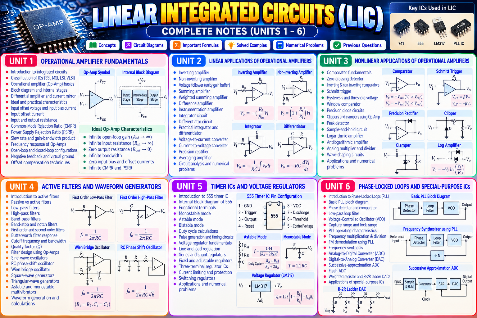
About this material
Linear Integrated Circuits (LIC) – Complete Study Material (Units 1–6)
Comprehensive study material covering operational amplifiers, integrated circuit characteristics, linear and nonlinear applications of op-amps, active filters, waveform generators, timers, voltage regulators and phase-locked loops. Includes circuit diagrams, important formulas, derivations, solved examples and numerical problem topics.
Unit 1 – Operational Amplifier Fundamentals
Introduction to integrated circuits
Classification of integrated circuits
Operational amplifier (Op-Amp) basics
Block diagram and internal stages of an Op-Amp
Differential amplifier and current mirror fundamentals
Ideal and practical Op-Amp characteristics
Input offset voltage and input bias current
Input offset current
Input and output resistance
Common-Mode Rejection Ratio (CMRR)
Power Supply Rejection Ratio (PSRR)
Slew rate and gain-bandwidth product
Frequency response of Op-Amps
Open-loop and closed-loop configurations
Negative feedback and virtual ground concept
Offset compensation techniques
Unit 2 – Linear Applications of Operational Amplifiers
Inverting amplifier
Non-inverting amplifier
Voltage follower
Summing amplifier
Weighted summing amplifier
Difference amplifier
Instrumentation amplifier
Integrator circuit
Differentiator circuit
Practical integrator and differentiator
Voltage-to-current converter
Current-to-voltage converter
Precision rectifier
Averaging amplifier
Op-Amp circuit analysis and numerical problems
Unit 3 – Nonlinear Applications of Operational Amplifiers
Comparator fundamentals
Zero-crossing detector
Inverting and non-inverting comparators
Schmitt trigger
Hysteresis and threshold voltage calculations
Window comparator
Precision diode circuits
Clippers and clampers using Op-Amps
Peak detector
Sample-and-hold circuit fundamentals
Logarithmic amplifier
Antilogarithmic amplifier
Analog multiplier and divider fundamentals
Wave-shaping circuits
Applications of nonlinear Op-Amp circuits
Unit 4 – Active Filters and Waveform Generators
Introduction to active filters
Passive versus active filters
Low-pass filters
High-pass filters
Band-pass filters
Band-stop and notch filters
First-order and second-order filters
Butterworth filter response
Filter cutoff frequency and bandwidth
Quality factor (Q)
Filter design using operational amplifiers
Sine-wave oscillators
RC phase-shift oscillator
Wien bridge oscillator
Square-wave generators
Triangular-wave generators
Astable and monostable multivibrator fundamentals
Waveform generation and frequency calculations
Unit 5 – Timer ICs and Voltage Regulators
Introduction to the 555 timer IC
Internal block diagram of the 555 timer
Functional terminals and operating principles
555 timer in monostable mode
555 timer in astable mode
Bistable operation
Duty-cycle calculations
Pulse generation and timing circuits
Voltage regulator fundamentals
Line regulation and load regulation
Series and shunt voltage regulators
Fixed and adjustable voltage regulators
Three-terminal regulator ICs
Current limiting and short-circuit protection
Switching regulator fundamentals
Voltage regulation applications
Unit 6 – Phase-Locked Loops and Special-Purpose ICs
Introduction to Phase-Locked Loops (PLL)
Basic PLL block diagram
Phase detector and phase comparator
Low-pass loop filter
Voltage-Controlled Oscillator (VCO)
PLL capture range and lock range
PLL operating characteristics
Frequency multiplication and division
FM demodulation using PLL
Frequency synthesis fundamentals
Analog-to-Digital Converter (ADC) basics
Digital-to-Analog Converter (DAC) basics
Successive-approximation ADC
Flash ADC fundamentals
Weighted-resistor and R-2R ladder DACs
Applications of special-purpose integrated circuits
Important Formulas and Concepts
Inverting amplifier gain: (A_v=-R_f/R_{in})
Non-inverting amplifier gain: (A_v=1+R_f/R_1)
Integrator output: (V_o=-\frac{1}{RC}\int V_i,dt)
Differentiator output: (V_o=-RC\frac{dV_i}{dt})
First-order filter cutoff frequency: (f_c=\frac{1}{2\pi RC})
555 monostable pulse width: (T\approx1.1RC)
555 astable frequency: (f\approx\frac{1.44}{(R_A+2R_B)C})
Note: These are standard introductory formulas. Use the exact circuit configuration and assumptions specified in your syllabus.
Learning Outcomes
Understand ideal and practical operational amplifier characteristics.
Analyze linear and nonlinear Op-Amp circuits.
Design active filters and waveform generators.
Explain 555 timer operation and calculate timing parameters.
Understand voltage regulators and power-supply circuits.
Analyze PLL operation and basic ADC/DAC architectures.
Solve circuit-based numerical problems and interpret waveforms.
This material is useful for class preparation, assignments, circuit analysis, laboratory preparation, revision and semester examination preparation.
Note: This is a general six-unit reference outline. The exact unit divisions, circuits and topics may vary according to your university syllabus.
Preview
13 files — tap a file to preview it
Files
Preview of Linear Integrated Circuits (LIC) – Complete Study Notes (Units 1–6)
Downloads
- Download
LIC unit5.pdf
PDF · 25.2 MB
- Download
Linear integrated circuits by Roy Chowdhary .pdf
PDF · 78.2 MB
- Download
6.lic.pdf
PDF · 15.0 MB
- Download
DocScanner Apr 1, 2023 5-19 PM_240212_153458.pdf
PDF · 9.4 MB
- Download
LIC NOTES 4.pdf
PDF · 11.3 MB
- Download
LIC_UNIT_1.pdf
PDF · 10.5 MB
- Download
LIC_UNIT_4 (1).pdf
PDF · 5.9 MB
- Download
lic_units_2&3.pdf
PDF · 18.3 MB
- Download
mid 2 notes.pdf
PDF · 33.5 MB
- Download
Applications of PLL.pdf
PDF · 3.5 MB
- Download
DC_DC_Converter_Performance_Parameters.pdf
PDF · 2 KB
- Download
LIC UNIT5-1 (1).pdf
PDF · 2.7 MB
- Download
UNIT 06 (1).pdf
PDF · 980 KB